20 KiB
Terraform Core Architecture Summary
This document is a summary of the main components of Terraform Core and how data and requests flow between these components. It's intended as a primer to help navigate the codebase to dig into more details.
We assume some familiarity with user-facing Terraform concepts like configuration, state, CLI workflow, etc. The Terraform website has documentation on these ideas.
Terraform Request Flow
The following diagram shows an approximation of how a user command is executed in Terraform:
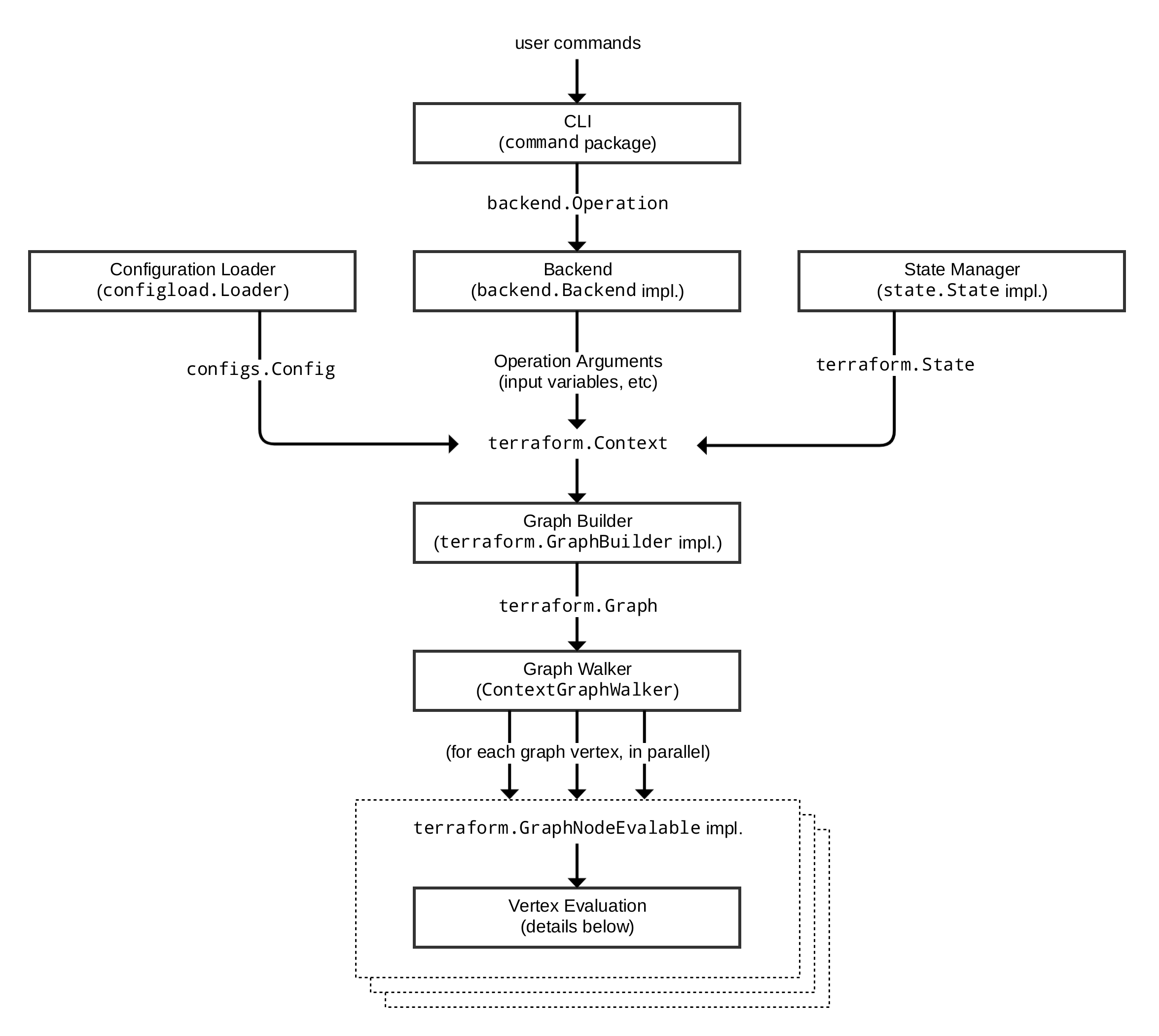
Each of the different subsystems (solid boxes) in this diagram is described in more detail in a corresponding section below.
CLI (command package)
Each time a user runs the terraform program, aside from some initial
bootstrapping in the root package (not shown in the diagram) execution
transfers immediately into one of the "command" implementations in
the command package.
The mapping between the user-facing command names and
their corresponding command package types can be found in the commands.go
file in the root of the repository.
The full flow illustrated above does not actually apply to all commands,
but it applies to the main Terraform workflow commands terraform plan and
terraform apply, along with a few others.
For these commands, the role of the command implementation is to read and parse
any command line arguments, command line options, and environment variables
that are needed for the given command and use them to produce a
backend.Operation
object that describes an action to be taken.
An operation consists of:
- The action to be taken (e.g. "plan", "apply").
- The name of the workspace where the action will be taken.
- Root module input variables to use for the action.
- For the "plan" operation, a path to the directory containing the configuration's root module.
- For the "apply" operation, the plan to apply.
- Various other less-common options/settings such as
-targetaddresses, the "force" flag, etc.
The operation is then passed to the currently-selected
backend. Each backend name
corresponds to an implementation of
backend.Backend, using a
mapping table in
the backend/init package.
Backends that are able to execute operations additionally implement
backend.Enhanced;
the command-handling code calls Operation with the operation it has
constructed, and then the backend is responsible for executing that action.
Backends that execute operations, however, do so as an architectural implementation detail and not a
general feature of backends. That is, the term 'backend' as a Terraform feature is used to refer to
a plugin that determines where Terraform stores its state snapshots - only the default local
backend and Terraform Cloud's backends (remote, cloud) perform operations.
Thus, most backends do not implement this interface, and so the command package wraps these
backends in an instance of
local.Local,
causing the operation to be executed locally within the terraform process itself.
Backends
A backend determines where Terraform should store its state snapshots.
As described above, the local backend also executes operations on behalf of most other
backends. It uses a state manager
(either
statemgr.Filesystem if the
local backend is being used directly, or an implementation provided by whatever
backend is being wrapped) to retrieve the current state for the workspace
specified in the operation, then uses the config loader to load and do
initial processing/validation of the configuration specified in the
operation. It then uses these, along with the other settings given in the
operation, to construct a
terraform.Context,
which is the main object that actually performs Terraform operations.
The local backend finally calls an appropriate method on that context to
begin execution of the relevant command, such as
Plan
or
Apply, which in turn constructs a graph using a graph builder,
described in a later section.
Configuration Loader
The top-level configuration structure is represented by model types in
package configs.
A whole configuration (the root module plus all of its descendent modules)
is represented by
configs.Config.
The configs package contains some low-level functionality for constructing
configuration objects, but the main entry point is in the sub-package
configload,
via
configload.Loader.
A loader deals with all of the details of installing child modules
(during terraform init) and then locating those modules again when a
configuration is loaded by a backend. It takes the path to a root module
and recursively loads all of the child modules to produce a single
configs.Config
representing the entire configuration.
Terraform expects configuration files written in the Terraform language, which
is a DSL built on top of
HCL. Some parts of the configuration
cannot be interpreted until we build and walk the graph, since they depend
on the outcome of other parts of the configuration, and so these parts of
the configuration remain represented as the low-level HCL types
hcl.Body
and
hcl.Expression,
allowing Terraform to interpret them at a more appropriate time.
State Manager
A state manager is responsible for storing and retrieving snapshots of the
Terraform state
for a particular workspace. Each manager is an implementation of
some combination of interfaces in
the statemgr package,
with most practical managers implementing the full set of operations
described by
statemgr.Full
provided by a backend. The smaller interfaces exist primarily for use in
other function signatures to be explicit about what actions the function might
take on the state manager; there is little reason to write a state manager
that does not implement all of statemgr.Full.
The implementation
statemgr.Filesystem is used
by default (by the local backend) and is responsible for the familiar
terraform.tfstate local file that most Terraform users start with, before
they switch to remote state.
Other implementations of statemgr.Full are used to implement remote state.
Each of these saves and retrieves state via a remote network service
appropriate to the backend that creates it.
A state manager accepts and returns a state snapshot as a
states.State
object. The state manager is responsible for exactly how that object is
serialized and stored, but all state managers at the time of writing use
the same JSON serialization format, storing the resulting JSON bytes in some
kind of arbitrary blob store.
Graph Builder
A graph builder is called by a
terraform.Context
method (e.g. Plan or Apply) to produce the graph that will be used
to represent the necessary steps for that operation and the dependency
relationships between them.
In most cases, the
vertices of Terraform's
graphs each represent a specific object in the configuration, or something
derived from those configuration objects. For example, each resource block
in the configuration has one corresponding
GraphNodeConfigResource
vertex representing it in the "plan" graph. (Terraform Core uses terminology
inconsistently, describing graph vertices also as graph nodes in various
places. These both describe the same concept.)
The edges in the graph represent "must happen after" relationships. These define the order in which the vertices are evaluated, ensuring that e.g. one resource is created before another resource that depends on it.
Each operation has its own graph builder, because the graph building process is different for each. For example, a "plan" operation needs a graph built directly from the configuration, but an "apply" operation instead builds its graph from the set of changes described in the plan that is being applied.
The graph builders all work in terms of a sequence of transforms, which
are implementations of
terraform.GraphTransformer.
Implementations of this interface just take a graph and mutate it in any
way needed, and so the set of available transforms is quite varied. Some
important examples include:
-
ConfigTransformer, which creates a graph vertex for eachresourceblock in the configuration. -
StateTransformer, which creates a graph vertex for each resource instance currently tracked in the state. -
ReferenceTransformer, which analyses the configuration to find dependencies between resources and other objects and creates any necessary "happens after" edges for these. -
ProviderTransformer, which associates each resource or resource instance with exactly one provider configuration (implementing the inheritance rules) and then creates "happens after" edges to ensure that the providers are initialized before taking any actions with the resources that belong to them.
There are many more different graph transforms, which can be discovered by reading the source code for the different graph builders. Each graph builder uses a different subset of these depending on the needs of the operation that is being performed.
The result of graph building is a
terraform.Graph, which
can then be processed using a graph walker.
Graph Walk
The process of walking the graph visits each vertex of that graph in a way
which respects the "happens after" edges in the graph. The walk algorithm
itself is implemented in
the low-level dag package
(where "DAG" is short for Directed Acyclic Graph), in
AcyclicGraph.Walk.
However, the "interesting" Terraform walk functionality is implemented in
terraform.ContextGraphWalker,
which implements a small set of higher-level operations that are performed
during the graph walk:
EnterPathis called once for each module in the configuration, taking a module address and returning aterraform.EvalContextthat tracks objects within that module.terraform.Contextis the global context for the entire operation, whileterraform.EvalContextis a context for processing within a single module, and is the primary means by which the namespaces in each module are kept separate.
Each vertex in the graph is evaluated, in an order that guarantees that the
"happens after" edges will be respected. If possible, the graph walk algorithm
will evaluate multiple vertices concurrently. Vertex evaluation code must
therefore make careful use of concurrency primitives such as mutexes in order
to coordinate access to shared objects such as the states.State object.
In most cases, we use the helper wrapper
states.SyncState
to safely implement concurrent reads and writes from the shared state.
Vertex Evaluation
The action taken for each vertex during the graph walk is called execution. Execution runs a sequence of arbitrary actions that make sense for a particular vertex type.
For example, evaluation of a vertex representing a resource instance during a plan operation would include the following high-level steps:
-
Retrieve the resource's associated provider from the
EvalContext. This should already be initialized earlier by the provider's own graph vertex, due to the "happens after" edge between the resource node and the provider node. -
Retrieve from the state the portion relevant to the specific resource instance being evaluated.
-
Evaluate the attribute expressions given for the resource in configuration. This often involves retrieving the state of other resource instances so that their values can be copied or transformed into the current instance's attributes, which is coordinated by the
EvalContext. -
Pass the current instance state and the resource configuration to the provider, asking the provider to produce an instance diff representing the differences between the state and the configuration.
-
Save the instance diff as part of the plan that is being constructed by this operation.
Each execution step for a vertex is an implementation of
terraform.Execute.
As with graph transforms, the behavior of these implementations varies widely:
whereas graph transforms can take any action against the graph, an Execute
implementation can take any action against the EvalContext.
The implementation of terraform.EvalContext used in real processing
(as opposed to testing) is
terraform.BuiltinEvalContext.
It provides coordinated access to plugins, the current state, and the current
plan via the EvalContext interface methods.
In order to be executed, a vertex must implement
terraform.GraphNodeExecutable,
which has a single Execute method that handles. There are numerous Execute
implementations with different behaviors, but some prominent examples are:
-
NodePlannableResource.Execute, which handles the
planoperation. -
NodeApplyableResourceInstance.Execute, which handles the mainapplyoperation. -
NodeDestroyResourceInstance.Execute, which handles the maindestroyoperation.
A vertex must complete successfully before the graph walk will begin evaluation for other vertices that have "happens after" edges. Evaluation can fail with one or more errors, in which case the graph walk is halted and the errors are returned to the user.
Expression Evaluation
An important part of vertex evaluation for most vertex types is evaluating any expressions in the configuration block associated with the vertex. This completes the processing of the portions of the configuration that were not processed by the configuration loader.
The high-level process for expression evaluation is:
-
Analyze the configuration expressions to see which other objects they refer to. For example, the expression
aws_instance.example[1]refers to one of the instances created by aresource "aws_instance" "example"block in configuration. This analysis is performed bylang.References, or more often one of the helper wrappers around it:lang.ReferencesInBlockorlang.ReferencesInExpr -
Retrieve from the state the data for the objects that are referred to and create a lookup table of the values from these objects that the HCL evaluation code can refer to.
-
Prepare the table of built-in functions so that HCL evaluation can refer to them.
-
Ask HCL to evaluate each attribute's expression (a
hcl.Expressionobject) against the data and function lookup tables.
In practice, steps 2 through 4 are usually run all together using one
of the methods on lang.Scope;
most commonly,
lang.EvalBlock
or
lang.EvalExpr.
Expression evaluation produces a dynamic value represented as a
cty.Value.
This Go type represents values from the Terraform language and such values
are eventually passed to provider plugins.
Sub-graphs
Some vertices have a special additional behavior that happens after their evaluation steps are complete, where the vertex implementation is given the opportunity to build another separate graph which will be walked as part of the evaluation of the vertex.
The main example of this is when a resource block has the count argument
set. In that case, the plan graph initially contains one vertex for each
resource block, but that graph then dynamically expands to have a sub-graph
containing one vertex for each instance requested by the count. That is, the
sub-graph of aws_instance.example might contain vertices for
aws_instance.example[0], aws_instance.example[1], etc. This is necessary
because the count argument may refer to other objects whose values are not
known when the main graph is constructed, but become known while evaluating
other vertices in the main graph.
This special behavior applies to vertex objects that implement
terraform.GraphNodeDynamicExpandable.
Such vertices have their own nested graph builder, graph walk,
and vertex evaluation steps, with the same behaviors as described in these
sections for the main graph. The difference is in which graph transforms
are used to construct the graph and in which evaluation steps apply to the
nodes in that sub-graph.